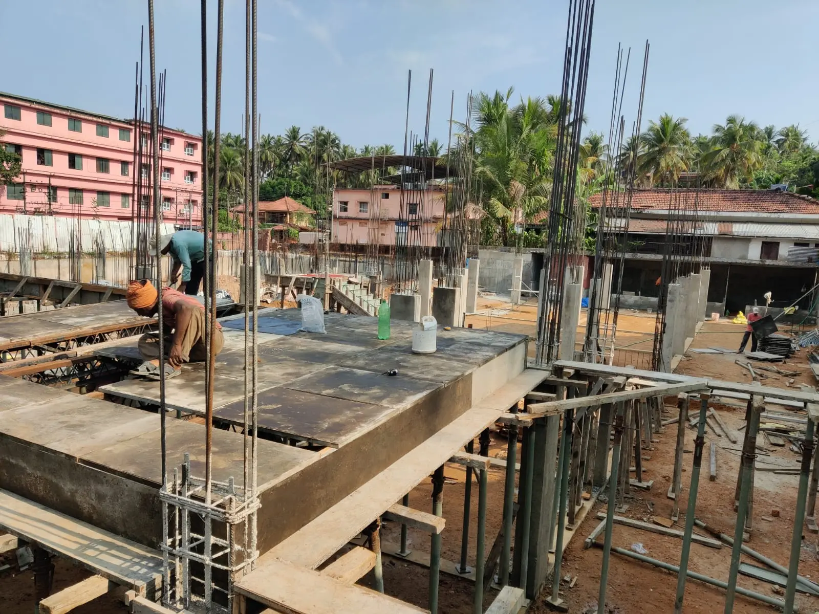
B+G+4 Residential Building:
Multi-Storey RC Frame
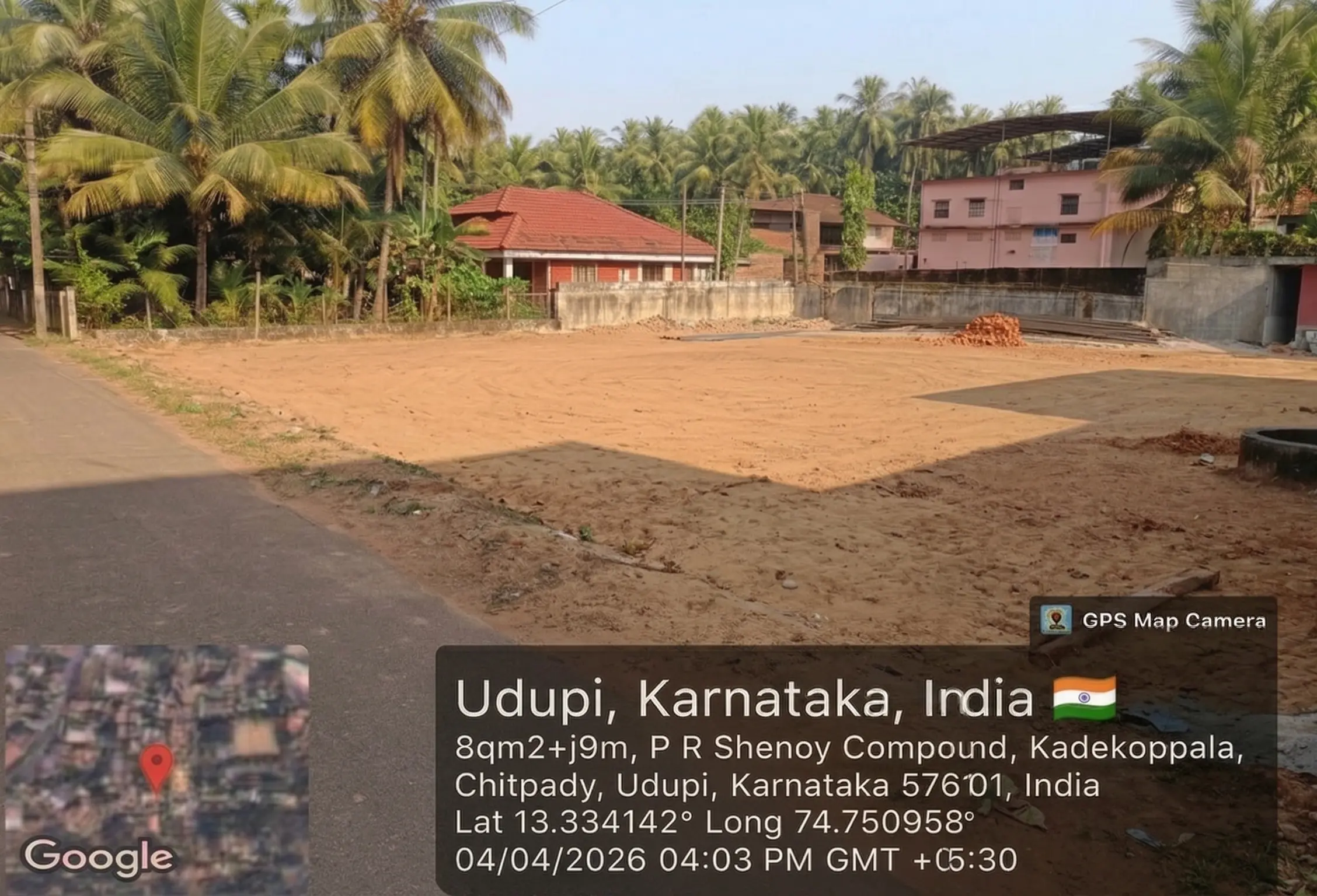
in Udupi, Karnataka
01 / The Client's BriefWhat the client needed
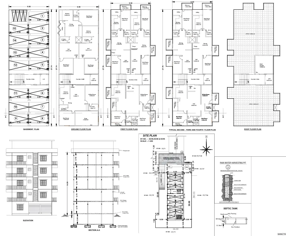
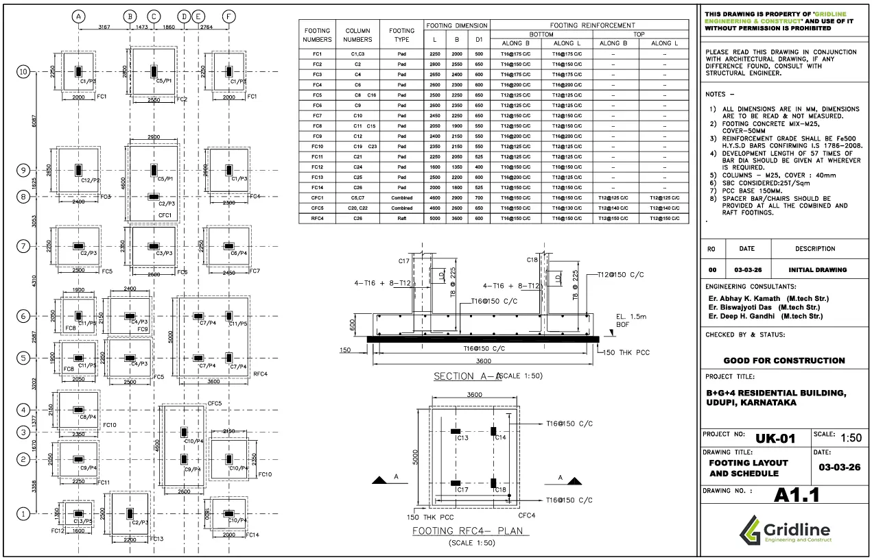
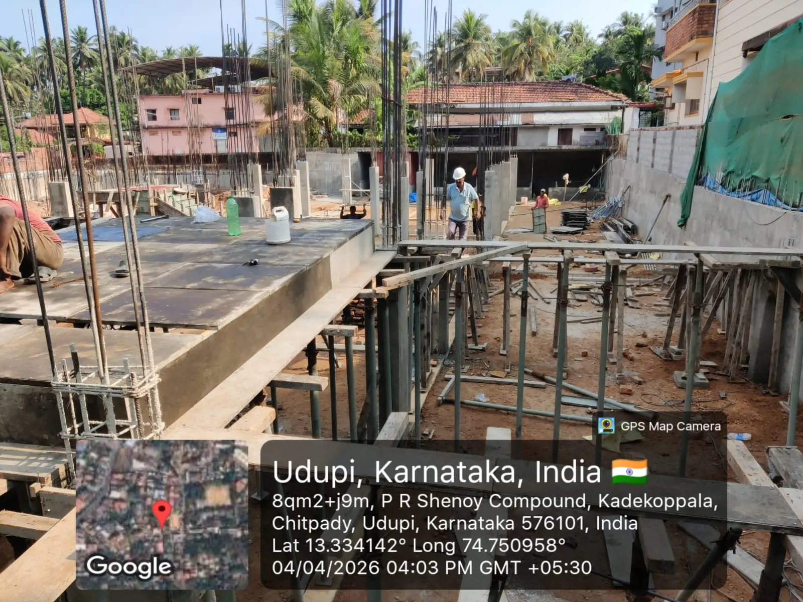
A developer in Udupi, Karnataka commissioned Gridline to provide complete structural engineering for a B+G+4 residential building — a basement, ground floor, and four upper floors totalling 4,326 square feet of built-up area. The site lies in coastal Karnataka, a region with specific exposure-class requirements for concrete durability under IS 456:2000 and seismic demands classified under Zone III per IS 1893:2016.
The brief was unambiguous: a structurally sound RC frame system, cost-optimised without sacrificing compliance, designed to accommodate the architectural floor plans without imposing structural constraints that would compromise the spatial programme.
"The structure must carry six floors safely in a coastal, seismic environment — every beam and column section has to be justified by calculation, not convention."
The client required complete good-for-construction drawings, a full bar bending schedule, and structural certification from a registered engineer — all delivered before site mobilisation.
02 / The Design ChallengeWhere the difficulty lived
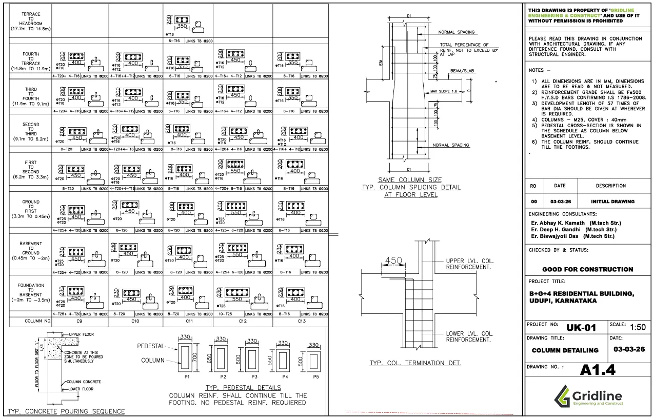
The most demanding constraint on this project was column geometry. The architectural brief required all columns to be flushed into the walls — meaning every column had to maintain a fixed width of 230mm to sit within the wall thickness without projection into the room. This ruled out any increase in column width as a route to increasing section capacity. All additional structural demand therefore had to be absorbed through column depth alone, while keeping depth within the limits dictated by the parking layout at ground level: column depths in the parking bays had to remain bounded to allow unobstructed vehicular manoeuvring. Simultaneously, the client required reduced steel quantities throughout — so sections could not simply be upscaled to resolve the capacity gaps created by the width restriction.
Each floor incorporated a sunken slab in the WC / bathroom areas — a waterproofing and drainage requirement that creates a discontinuity in slab level and introduces torsion and differential deflection at the slab edge that must be explicitly designed for, rather than assumed to self-resolve. Across six floors, this meant twenty-plus individual sunken slab perimeter conditions requiring detailing.
The cantilever beams posed a distinct challenge. Several cantilever beams were taken perpendicular off primary beams — not off columns — meaning the cantilever load transferred as an eccentric point load and torsional moment into the primary beam rather than a direct column reaction. Because these cantilevers had no continuity into adjacent spans, the primary beams carrying them had to be designed for the full torsional demand without relying on frame action for relief. Torsion design of RC beams per IS 456 Clause 41 was applied explicitly for each affected primary member.
03 / Our SolutionHow Gridline delivered
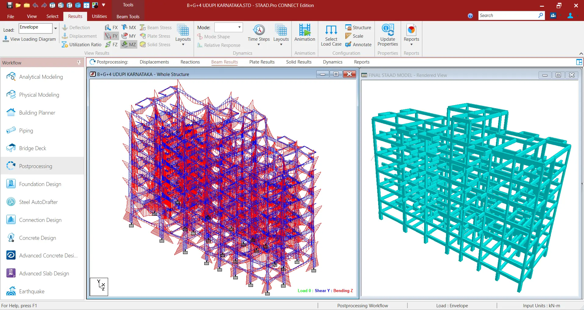
The 230mm column width constraint was held as non-negotiable throughout design. Column depths were varied floor by floor within the parking and habitable zones to satisfy capacity requirements within the architectural envelope — deeper in the lower floors where axial loads are highest, tapered as the structure rises. Steel quantities were controlled by running independent manual hand calculation checks alongside the STAAD.Pro model output, allowing over-designed members to be identified and reduced without compromising code compliance. Every member was verified by two independent methods before inclusion in the GFC drawings.
The sunken WC slabs were detailed as isolated panels with thickened perimeter bands and step reinforcement at the slab edge to resist the differential deflection and crack the junction. Each sunken zone was treated as a separate loading condition in the floor design, with the surrounding flat slab continuity interrupted and compensated through additional top steel at the perimeter.
For the cantilever beams projecting perpendicular from primary beams, the torsional design of the supporting primary beam was resolved per IS 456:2000 Clause 41 using the equivalent shear method — the torsional moment was converted to an equivalent shear and the beam stirrups and longitudinal steel sized accordingly. Where torsional demand was high, closed stirrups were detailed explicitly, and the cantilever root connection to the primary beam was reinforced with additional hanger bars to prevent face shear failure. The complete BBS was issued with all special conditions flagged zone-by-zone for site teams.

From analysis to delivered drawings
Need a multi-storey RC structure designed?
From basement to rooftop slab — Gridline delivers IS 456-compliant structural drawings with full STAAD.Pro analysis, BBS, and engineer certification. Seismic Zone III and V experience.